Slim Shoe Cabinet Plans: 13 Easy DIY Steps
SMALL SPACES & STORAGE
Slim Shoe Cabinet Plans: 13 Easy DIY Steps
These slim shoe cabinet plans create a 25 cm-deep storage cabinet that keeps footwear organized without blocking normal hallway traffic.
By Practical Wood Plans · Verify every dimension against your material and hardware before building.
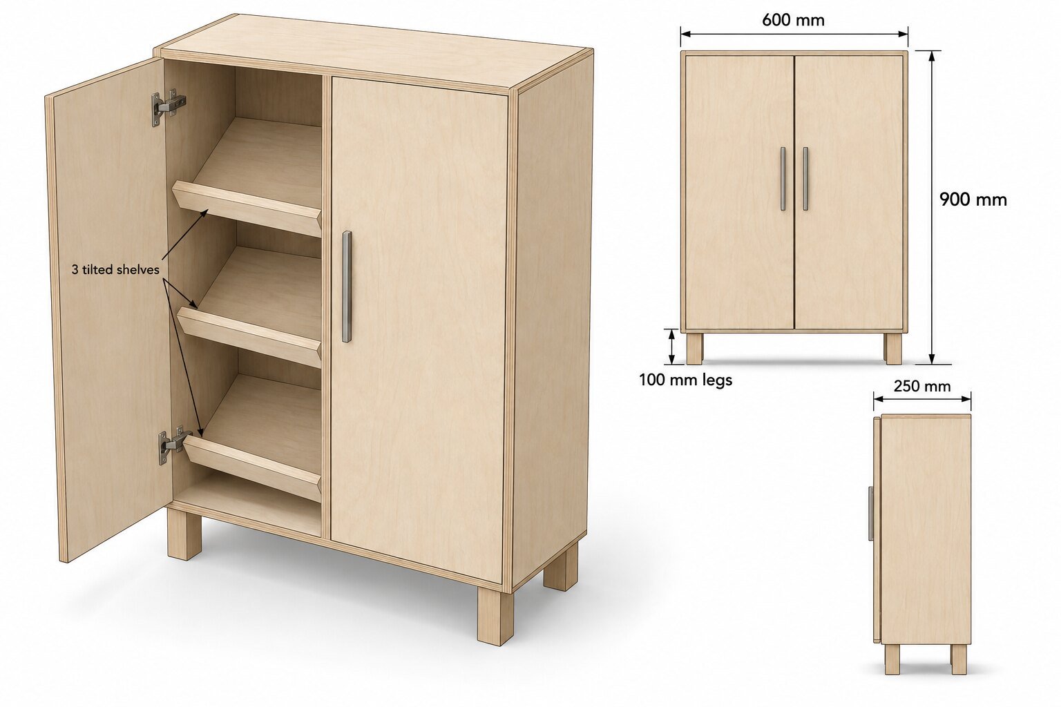
If your entryway is too narrow for a full-depth shoe cabinet, this build solves that problem directly. It’s a slim shoe cabinet — just 25 cm deep — designed to slide against a hallway wall without blocking foot traffic, while still holding a full family’s daily shoe rotation behind two clean, flat doors.
The finished cabinet measures 60 cm wide, 25 cm deep, and 90 cm tall, and its flat top doubles as a spot to drop keys, mail, or a small tray. Inside, three tilted shelves with front lips keep shoes angled and contained rather than sliding forward every time the door opens.
This is a beginner-to-intermediate project. If you can run a pocket-hole jig, cut plywood square, and hang a cabinet hinge, you can build this in a weekend. It requires no lift mechanisms, no drawer slides, and no complex joinery — just a plywood box, three angled shelves, two flat doors, and four short legs. It’s an ideal first “real” furniture project, and a genuinely useful one for tight apartments, mudrooms, or behind-the-door hallway corners.
1. Project Overview
| Project | Slim Shoe Cabinet for a Narrow Entryway |
| Finished size | 60 cm W x 25 cm D x 90 cm H |
| Difficulty | Beginner–Intermediate |
| Estimated build time | 6–8 hours, plus finish drying/curing time |
| Estimated cost | 70–110 USD depending on plywood grade and hardware |
| Recommended material | 18 mm birch or oak-veneer plywood, 6 mm plywood back |
| Primary joinery | Pocket-hole joinery + glue, rabbeted back panel |
| Best for | Narrow hallways, apartment entryways, behind-door corners |
These slim shoe cabinet plans produce a simple rectangular cabinet standing on four short legs. Two flat overlay doors span the front and swing open on concealed cup hinges to reveal three shoe shelves, each tilted slightly toward the front and fitted with a raised lip so shoes rest at an angle rather than lying flat and sliding out. The flat top surface sits at a comfortable 90 cm — perfect height for a small entryway tray, a lamp, or a dish for keys.
2. Finished Dimensions
- Overall width: 60 cm
- Overall depth: 25 cm
- Overall height: 90 cm (80 cm cabinet box + 10 cm legs)
Key internal dimensions:
- Internal clear width: 56.4 cm
- Internal clear height (shelf cavity): 76.4 cm
- Internal clear depth: 25 cm (shelves are cut to 24 cm to allow for the tilt and back clearance)
- Shelf spacing: approximately 19 cm between shelves, giving three compartments generous enough for sneakers, flats, and most boots
A 25 cm depth is the sweet spot for this kind of cabinet — deep enough to hold an adult shoe on a slight angle, but shallow enough to fit against a wall in a hallway as narrow as 70–80 cm wide without becoming an obstacle. These dimensions are now locked and are used consistently in every table, drawing, and instruction below.
3. Design & Construction Overview
The slim shoe cabinet plans use a simple five-panel box: two side panels, a top, a bottom, and a back panel, joined with pocket-hole screws and glue, with the thin back panel seated in a rabbet to lock everything square. Four short hardwood legs are glued and screwed to corner blocks under the bottom panel, lifting the cabinet slightly off the floor for easy cleaning underneath and a lighter visual footprint.
Inside the box, three plywood shelves are tilted back-to-front by about 8–10° and supported on simple screwed cleats along each side panel — no dado grooves are needed. Each shelf has a 3 cm front lip glued and screwed to its leading edge, which stops shoes from sliding forward when the door opens. The front of the cabinet is closed by two flat slab doors (no frame-and-panel construction, keeping this approachable for beginners), hung on standard 35 mm cup overlay hinges, with a bar handle mounted on each door near the center gap.
In these slim shoe cabinet plans, the construction sequence is: build and square the box first, attach the back panel to lock it square, mount the legs, install the shelf cleats and shelves, then hang the doors and add handles last, once everything else is finished and stable.
4. Shopping List
| Material Nominal/Actual Size Approx. Quantity Purpose | |||
|---|---|---|---|
| Plywood (birch or oak veneer) | 18 mm, full sheet 122 x 244 cm | 1 sheet | Sides, top, bottom, shelves, lips, doors |
| Plywood (utility grade) | 6 mm, approx. 60 x 80 cm offcut/panel | 1 small panel | Back panel |
| Hardwood strip | 4 x 4 cm, approx. 45 cm length | 1 length | Four legs |
| Wood glue | Standard PVA wood glue | 1 bottle | All glued joints |
| Edge banding (optional) | Iron-on veneer edge tape, 22 mm wide | 1 roll (5 m) | Covering visible plywood edges |
The slim shoe cabinet plans include a small waste allowance; the single 18 mm sheet covers roughly 1.6 m² of actual parts against a total sheet area of nearly 3 m², leaving comfortable margin for square cuts and a few offcuts for future small projects.
5. Hardware List
| Item Size / Spec Quantity Purpose | |||
|---|---|---|---|
| Pocket-hole screws | 32 mm coarse thread | 24 | Box carcass assembly |
| Wood screws | 4 x 40 mm | 20 | Cleats, corner blocks, leg mounting |
| Overlay cup hinges | 35 mm cup, standard overlay | 4 (2 per door) | Hanging the doors |
| Bar handles | 12 cm center-to-center | 2 | Door pulls |
| Wood screws (fine) | 4 x 16 mm (usually supplied with handles) | 4 | Handle mounting |
| Shelf cleats (cut from scrap) | 18 mm x 3 cm x 24 cm | 6 (2 per shelf) | Supporting the tilted shelves |
| Corner blocks (cut from scrap) | 18 mm x 4 cm x 4 cm | 4 | Leg attachment points |
Only hardware genuinely required by these slim shoe cabinet plans is listed — there are no drawer slides, lift mechanisms, or shelf pins in this design, since the shelves are fixed and the doors are simple swinging overlay doors.
6. Complete Cut List
| Part ID Part Name Qty Thickness Width Length Material Notes | |||||||
|---|---|---|---|---|---|---|---|
| A | Side Panel | 2 | 18 mm | 25 cm | 80 cm | Plywood | Full box height |
| B | Top Panel | 1 | 18 mm | 25 cm | 56.4 cm | Plywood | Fits between sides |
| C | Bottom Panel | 1 | 18 mm | 25 cm | 56.4 cm | Plywood | Fits between sides |
| D | Back Panel | 1 | 6 mm | Measure after routing | Measure after routing | Plywood | Typical approx. 57.6 x 77.6 cm; fit to actual rabbet |
| E | Shelf | 3 | 18 mm | 24 cm | 56 cm | Plywood | Tilted, rests on cleats |
| F | Shelf Front Lip | 3 | 18 mm | 3 cm | 56 cm | Plywood | Glued/screwed to shelf front edge |
| G | Door | 2 | 18 mm | 79 cm | 29.7 cm | Plywood | Flat slab overlay door |
| H | Leg | 4 | — | 4 cm | 10 cm | Hardwood (4×4 cm stock) | Corner legs |
| I | Shelf Cleat | 6 | 18 mm | 3 cm | 24 cm | Plywood offcut | 2 per shelf, screwed to sides |
| J | Corner Block | 4 | 18 mm | 4 cm | 4 cm | Plywood offcut | Leg mounting points |
Verification: Sides (80 cm) + top/bottom insets reconstruct the 60 cm overall width (56.4 + 2 x 1.8 = 60 cm) and 80 cm box height. Doors (29.7 x 2 + 0.3 gap + 0.3 reveal = 60 cm) reconstruct overall width exactly. Legs (10 cm) plus box height (80 cm) reconstruct overall height (90 cm). All numbers check out against the locked master specification.
7. Tools Required
Essential tools:
- Circular saw or table saw (straight, square cuts in plywood)
- Pocket-hole jig and drill/driver
- Tape measure, combination square, pencil
- Clamps (at least 4, bar or F-clamps)
- Drill with countersink bit
- Sandpaper (120, 180, 220 grit) or random orbit sander
- Hinge-boring bit (35 mm Forstner bit) or a hinge jig template
Helpful optional tools:
- Track saw for straighter plywood edge cuts
- Router with a rabbeting bit (for the back panel rabbet — a table saw dado stack or even a straight bit and multiple passes works too)
- Iron and edge-banding trimmer (if using edge tape)
- Orbital sander (speeds up the sanding stage significantly)
If you don’t own a track saw, a straightedge clamped to the plywood and guided with a circular saw produces equally straight cuts — it just takes a little longer.
8. Slim Shoe Cabinet Plans and Technical Drawings
IMAGE 1 — MASTER DIMENSION DRAWING 3/4 perspective technical line drawing of the complete cabinet, showing overall width (60 cm), depth (25 cm), and height (90 cm), with the two front doors, visible leg height (10 cm), and top surface clearly labeled.
IMAGE 2 — FRONT VIEW Straight-on technical elevation showing the two doors (29.7 cm each), the 3 mm center gap, overall width (60 cm), and overall height (90 cm), with leg height called out separately (10 cm).
IMAGE 3 — SIDE VIEW Profile technical elevation showing the 25 cm overall depth, the tilt angle of the three internal shelves (8–10°), and the 10 cm leg height.
IMAGE 4 — TOP VIEW Plan view showing the 60 cm width and 25 cm depth of the top panel, with wall-placement clearance notes for a narrow hallway.
IMAGE 5 — INTERNAL / STORAGE DETAIL Cutaway side view showing the three tilted shelves with front lips inside the cavity, shelf spacing (~19 cm), the cleat mounting method, and the 76.4 cm internal cavity height.
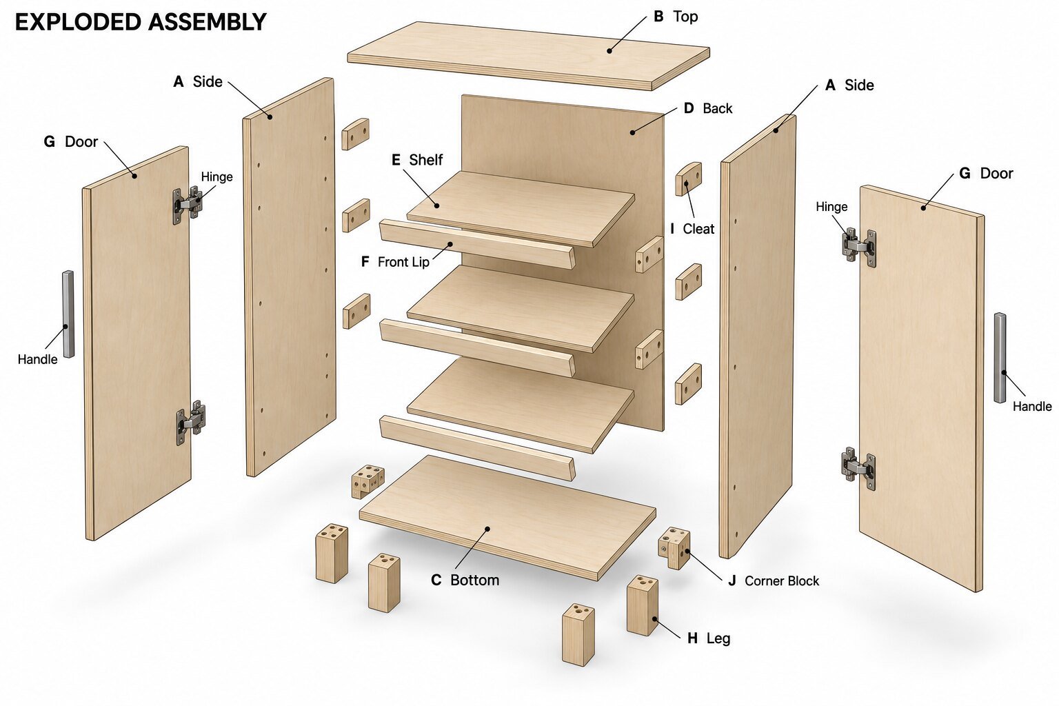 Exploded assembly: carcass, back, cleats, three tilted shelves, doors, and legs.
9. Step-by-Step Build Instructions
Step 1 – Cut All Plywood Parts to Size
Purpose: Break down the plywood sheet into every part on the cut list before any assembly begins.
Parts used: A, B, C, D, E, F, G, I, J
Instructions: For these slim shoe cabinet plans, work from the cut list in Section 6, cut the two Side Panels (A) at 25 x 80 cm first, since they’re the largest and set the grain direction for the rest of the layout. 7 cm, the three Shelves (E) at 24 x 56 cm, the three Shelf Lips (F) at 3 x 56 cm, the six Shelf Cleats (I) at 3 x 24 cm, and the four Corner Blocks (J) at 4 x 4 cm.
6 cm, but the actual opening controls the final cut. Label each piece in pencil on the inside face as you cut it.
Check before moving on: Every part matches its listed dimension within 1 mm, all edges are square (check with a combination square), and pieces are clearly labeled to avoid mix-ups later.
Step 2 – Drill Pocket Holes in the Top and Bottom Panels
Purpose: Prepare the Top (B) and Bottom (C) panels for hidden screw joinery into the Side Panels (A).
Parts used: B, C
Instructions: Set the pocket-hole jig for 18 mm material. Drill three pocket holes along each end of both the Top (B) and Bottom (C) panels — these holes go on the underside face (for the top panel) and top face (for the bottom panel), so they end up hidden inside the finished cabinet. Space the three holes evenly across the 25 cm depth, roughly 4 cm, 12.5 cm, and 21 cm from the front edge.
Check before moving on: All 12 pocket holes (3 per end x 2 ends x 2 panels) are drilled on the correct hidden face, and the jig depth setting matches 18 mm material so the screw won’t blow through the opposite face.
Step 3 – Cut the Back-Panel Rabbet in the Side, Top, and Bottom Panels
Purpose: Create a 6 mm deep rabbet along the rear inside edge of the Side Panels (A), Top Panel (B), and Bottom Panel (C) so the Back Panel (D) sits flush and locks the box square.
Parts used: A, B, C
Instructions: Using a router with a rabbeting bit (or a table saw dado stack), cut a rabbet 6 mm deep and 6 mm wide along the rear inside edge of both Side Panels, and along the rear edge of the Top and Bottom Panels. This rabbet should run the full length of each piece on the inside face only.
Check before moving on: The 6 mm Back Panel offcut test-fits flush into the rabbet on all four pieces with no forcing and no visible gap.
Step 4 – Assemble the Box (Sides, Top, Bottom)
Purpose: Join the two Side Panels (A) to the Top (B) and Bottom (C) panels using pocket screws and glue, forming the main cabinet box.
Parts used: A, B, C
Instructions: Apply wood glue along the mating edges. Position the Top Panel (B) between the two Side Panels (A), flush with the top ends, with the rabbeted edges all facing the rear. Clamp square, then drive the pocket screws from Step 2 through the Top Panel into each Side Panel. Repeat for the Bottom Panel (C), flush with the bottom ends. Check the whole box for square using a combination square at all four inside corners before the glue sets.
Check before moving on: The box is square (equal diagonal measurements corner to corner), all four joints are tight with no visible gap, and the rabbets all align along the same rear plane.
Step 5 – Fit and Fasten the Back Panel
Purpose: Install the Back Panel (D) into the rabbet to lock the box permanently square.
Parts used: D
Instructions: Measure the completed rabbet, cut the Back Panel (D) with about 0.5 mm fitting clearance, and dry-fit it without force. Once the carcass is square, apply a thin bead of glue and secure the 6 mm panel with 18–20 mm brads, narrow-crown staples, or short pan-head screws about every 15 cm. Do not use 40 mm screws through a thin back near a narrow rabbet shoulder.
Check before moving on: The box remains square after the back panel is fixed, the back panel sits flush with the rear face of the sides/top/bottom, and no fasteners protrude through the front.
Step 6 – Build and Attach the Corner Blocks
Purpose: Create solid mounting points inside the bottom corners of the cabinet for the legs.
Parts used: C, J
Instructions: Glue and screw the four Corner Blocks (J) into the inside bottom corners of the box, flush against both the Bottom Panel (C) and the inside face of the Side Panels, using two 4 x 40 mm screws per block driven up through the bottom panel into each block.
Check before moving on: All four blocks sit tight in their corners with no rocking, and none interfere with where the shelf cleats will go later.
Step 7 – Attach the Legs
Purpose: Mount the four Legs (H) to the corner blocks, lifting the cabinet 10 cm off the floor.
Parts used: H, J
Instructions: With the box still upside down, position each Leg (H) against a Corner Block (J), inset 2 cm from both outer edges of the box. Glue the mating faces, clamp, and drive two 4 x 40 mm screws through the corner block into each leg.
Check before moving on: All four legs are the same height (10 cm) and sit at matching insets, so the box rests level and flat when turned right-side up.
Step 8 – Install the Shelf Cleats
Purpose: Provide screwed support ledges inside the box for the three tilted Shelves (E).
Parts used: I
Instructions: Turn the box right-side up. On the inside face of each Side Panel, mark cleat positions at approximately 19 cm, 38 cm, and 57 cm up from the interior floor, tilting each mark so the front edge of the cleat sits about 2 cm lower than the rear edge (creating the shelf tilt). Glue and screw one Shelf Cleat (I) at each marked position on both sides, using two 4 x 40 mm screws per cleat.
Check before moving on: Cleats on opposite sides are at matching heights and matching tilt, verified by placing a straightedge across from one side to the other — it should sit level side-to-side even though it’s tilted front-to-back.
Step 9 – Assemble and Install the Shelves
Purpose: Attach the front lips to the shelves, then drop the finished shelves into place on the cleats.
Parts used: E, F
Instructions: Glue and screw each Shelf Front Lip (F) to the front edge of its matching Shelf (E), using screws driven up through the underside of the shelf into the lip so no fasteners show on top. Once all three lip assemblies are dry, set each shelf onto its pair of cleats inside the box, front lip facing forward and down-tilted as designed.
Check before moving on: Each shelf sits flush and stable on its cleats with no rocking, the lips are all facing the same direction, and there is visible clearance between the top shelf and the underside of the Top Panel for shoes to be placed by hand.
Step 10 – Sand All Surfaces
Purpose: Prepare every visible surface for finishing.
Parts used: All parts
Instructions: Sand the entire cabinet, doors, and shelves progressively through 120, 180, and 220 grit, paying particular attention to the door edges, the shelf lips, and the top surface, since these get the most contact. Fill any visible screw holes or minor gaps with wood filler before the final 220-grit pass. See Section 10 for full detail.
Check before moving on: All surfaces feel smooth to the touch with no sharp plywood edges, and dust has been fully wiped down before moving to hinge installation.
Step 11 – Apply the Finish
Purpose: Protect and seal all wood surfaces.
Parts used: All parts
Instructions: Apply the chosen finish (see Section 11) to the cabinet body, shelves, and doors separately, following the product’s recommended number of coats and dry times between coats. Keep the doors separate from the body during finishing so both sides can be coated evenly.
Check before moving on: All coats are fully dry and cured per the product label before hardware installation begins, and the finish is even with no drips or tacky patches.
Step 12 – Mount the Hinges and Hang the Doors
Purpose: Attach the two Doors (G) to the cabinet using overlay cup hinges.
Parts used: G
Instructions: Bore two 35 mm hinge-cup holes into the back of each door, positioned 10 cm from the top and bottom edges. Screw the hinge cups into the doors, then position each door on the cabinet with a 1.5 mm reveal at the outer edge and a 1.5 mm reveal at the center gap (3 mm total between the two doors), and screw the hinge mounting plates to the inside face of the Side Panels.
Check before moving on: Both doors swing freely without binding, close with an even 3 mm center gap, and sit flush with the front edges of the top, bottom, and side panels all around.
Step 13 – Attach the Handles and Final Checks
Purpose: Add door pulls and perform the final assembly check.
Parts used: G
Instructions: Mark handle centers 3 cm in from the inner edge of each door (nearest the center gap), vertically centered, and screw on the bar handles using the fasteners supplied with the hardware. Open and close both doors several times, load a few pairs of shoes onto each shelf, and complete the Final Assembly Check in Section 15.
Check before moving on: Handles are level and at matching heights on both doors, doors close evenly, and the cabinet passes every item on the final checklist.
10. Sanding & Preparation
Sand in three passes: 120 grit to remove mill marks and flatten any glue squeeze-out, 180 grit to smooth the surface generally, and 220 grit as a final pass before finishing. Pay extra attention to the plywood edges on the doors and top panel, since exposed plywood layers can catch clothing if left rough — round them very slightly with fine sandpaper or a sanding sponge.
Fill visible pocket-screw holes and any small gaps with wood filler matched to your plywood tone, let it cure fully, then sand it flush during the 180-grit pass. Vacuum and wipe down every surface with a tack cloth immediately before finishing — any dust left on the surface will show up under a clear finish.
11. Finishing
For this cabinet, a water-based polyurethane in a satin sheen is the most practical choice: it dries quickly, doesn’t yellow light plywood veneers over time, and stands up well to the daily wear of an entryway (door swings, shoe scuffs, the occasional wet umbrella). Apply two to three thin coats with a foam brush or lint-free cloth, sanding lightly with 320 grit between coats.
If you prefer a more natural look, a hardwax oil finish penetrates the wood rather than sitting on top, and is easy to spot-repair later if the top surface gets scratched from keys or mail. For a bolder entryway statement, paint (a solid color, applied over a plywood-appropriate primer) hides plywood grain entirely and is a good option if you want the cabinet to match existing trim or wall color rather than show off the wood itself.
Avoid oil-based polyurethane here unless you don’t mind some amber yellowing over the years, since this piece typically stays in view daily.
12. Safety
Follow the OSHA woodworking safety guidance for machine guarding, dust control, and safe tool operation. Secure this tall, shallow cabinet to a wall stud or a correctly rated structural fixing before use.
This build involves a few risks specific to its actual construction, beyond generic shop safety. Plywood dust from cutting and sanding contains fine particles that are more irritating than solid-wood dust — wear a proper dust mask or a shop vacuum with dust collection at the saw, especially when using a router to cut the back-panel rabbet, which generates a continuous stream of fine dust. When boring the 35 mm hinge-cup holes with a Forstner bit, clamp the door securely and back it with a sacrificial scrap underneath to prevent tear-out and to stop the bit from grabbing and spinning the door unexpectedly.
Because the cabinet stands on four fairly short, inset legs, always fully load-test it on a level floor before placing it into daily use — press down firmly on one corner of the loaded top to confirm it doesn’t rock or tip before children or pets are around it. Finally, ventilate the room well when applying any solvent-based or oil finish, and let the cabinet fully off-gas per the product’s cure time before it goes into a small, enclosed entryway.
13. Common Mistakes
| Problem Why It Happens How to Prevent It How to Fix It | |||
|---|---|---|---|
| Cabinet isn’t square | Box was fastened before checking diagonals, or the back panel was forced in unevenly | Check diagonal measurements before glue sets in Step 4; let the back panel guide squareness in Step 5 | Loosen clamps, re-square, and re-clamp before glue fully cures; if already cured, add a temporary diagonal brace to pull it back into square |
| Doors bind or won’t close evenly | Hinge cups bored at inconsistent depth or position between the two doors | Use a hinge jig or template so both doors are bored identically | Adjust the hinge’s built-in depth/side screws — most overlay hinges have three-way adjustment for exactly this |
| Uneven gap between the two doors | Doors were installed by eye rather than measured from a centerline | Measure and mark the 3 mm center gap on the cabinet face before mounting either door | Loosen the hinge mounting plate screws and shift the door slightly, then re-tighten |
| Shelves rock or sit unevenly | Cleats on opposite sides were installed at slightly different heights | Use a level or story stick to mark both sides at the same time in Step 8 | Remove the shelf, add a thin shim under the low-side cleat, and re-glue/screw |
| Shoes slide off the shelf despite the lip | Shelf tilt angle was cut or installed too shallow | Confirm the 2 cm front-to-back drop across the 24 cm shelf depth when marking cleats | Add a slightly taller lip strip, or shim the rear cleat higher to increase the tilt |
| Plywood edges look rough or chip out | Cutting with a dull blade or without a zero-clearance/scoring pass | Use a sharp, fine-tooth plywood blade and score the top face first on visible cuts | Sand the chipped edge smooth and apply edge banding to hide it cleanly |
14. Size Modifications
Dimensions that can easily change:
- Overall height can be adjusted by changing leg length (H) — taller legs simply raise the whole cabinet without affecting anything else.
- Finish and handle style can be swapped freely with no structural impact.
Dimensions that require recalculation:
- Overall width: changing this changes the Top (B) and Bottom (C) panel lengths, the Shelf (E) and Lip (F) lengths, and both Door (G) widths — recalculate all of these together, keeping the 3 mm center gap and 1.5 mm reveals in the door math.
- Overall depth: changing this changes the Side Panel (A) depth, Top/Bottom depth, Back Panel width, and the shelf tilt geometry — shelves deeper than about 30 cm should have their tilt angle reduced slightly so they don’t feel too steep.
- Number of shelves: adding a shelf means recalculating spacing within the 76.4 cm cavity height and adding matching cleats and lips.
Dimensions that should remain unchanged:
- The 18 mm carcass thickness and 6 mm back panel thickness — thinner material will flex under shoe loads and won’t hold pocket screws reliably.
- The 3 mm door gap and 1.5 mm reveals — these are set by the hinge hardware’s overlay range and shouldn’t be reduced further.
If you resize the width significantly (for example, widening to fit a longer hallway wall), consider adding a center vertical divider for extra rigidity and a third door, since an unsupported plywood span wider than about 90 cm can begin to flex over time.
15. Final Assembly Check
Before calling this cabinet finished, confirm the following:
16. Project Drawings
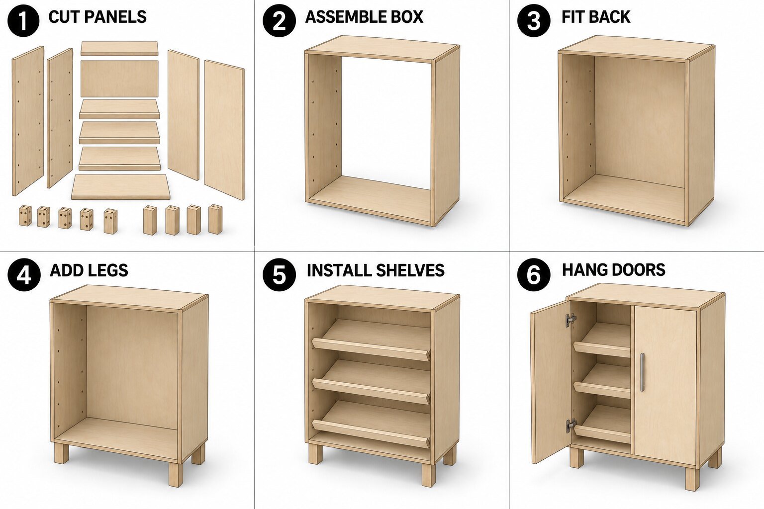 Visual build sequence from panel preparation through final door installation.
17. FAQ
Is 18 mm plywood strong enough for the shelves, or should I use something thicker? 18 mm plywood is plenty strong for shoe loads at this shelf width (56 cm) because each shelf is supported by cleats along both sides rather than spanning unsupported — the load is carried close to its edges, not in the middle of a long, thin span.
Can I build this without a router, since I don’t own one for the back-panel rabbet? Yes — you can skip the rabbet entirely and simply glue and screw the 6 mm back panel flush to the rear edges of the box instead of recessing it. The cabinet will be just as square and stable; you’ll just see a thin back-panel edge line around the rear perimeter.
How much does this project typically cost to build? Most builders land between $70 and $110 USD, with the plywood sheet and hinges being the biggest cost drivers; using a lower grade of plywood or reusing an offcut you already have can bring that down further.
Is this a good first furniture project for a beginner? Yes — there are no drawer slides, no lift mechanisms, and no complex joinery to fight with. The trickiest steps are keeping the box square and boring accurate hinge holes, both of which are common, well-documented beginner skills.
Can I use solid wood instead of plywood? You can, but solid wood adds cost and requires accounting for seasonal wood movement, especially on the wide Top and Bottom panels — plywood is more dimensionally stable and is the more practical choice for a piece this size.
Will this cabinet hold up under heavy boots, not just sneakers and flats? Yes, within reason — the 19 cm shelf spacing comfortably fits most sneakers, flats, and ankle boots. Taller boots will need to be stored on their side or in the bottom compartment, which has the most headroom above it.
What if my hallway is narrower than 25 cm of clearance? You can reduce the depth to as little as 20 cm, but you’ll need to reduce the shelf tilt angle slightly and expect shoes to sit a bit more upright rather than fully angled — see Section 14 for what to recalculate.
Do I need special hinges, or will standard cabinet hinges from a hardware store work? Standard 35 mm cup overlay hinges from any hardware store work fine — there’s nothing specialized about the hardware in this build.
18. Related Woodworking Plans
- Narrow Console Table for a Small Hallway
- Wall-Mounted Entryway Organizer with Hooks and Cubbies
- Slim Bathroom Storage Cabinet for Small Spaces
- Fold-Down Wall Desk for Tight Apartments
- Stackable Closet Shoe Cubbies
- Under-Stairs Storage Drawer Unit